It is an implementation note of SPH using UE5 Niagara System, related about usage of Simulation Stage, Grid 3D, screen space rendering using depth buffer and so on.
Github repository: https://github.com/CheapMeow/UE5-NiagaraSPH
I also learn other’s tutorial: https://www.bilibili.com/video/BV1pr4y1v78B
SPH Introduction
Basic knowledge about SPH can see other tutorial.
Matthias Müller et al, “Particle-based fluid simulation for interactive applications”
Niagara System Setup
Basic knowledge about Niagara System can see other tutorial.
To setup, change Sim Target to GPUCompute Sim, because our Niagara System may calculate millions of particles.
Change Calculate Bounds Mode to Fixed, because particles are upload to GPU so it is hard to calculate bounds every frame.
Change Life Cycle Mode to Self, in order to set Loop Behaviour as Infinite.
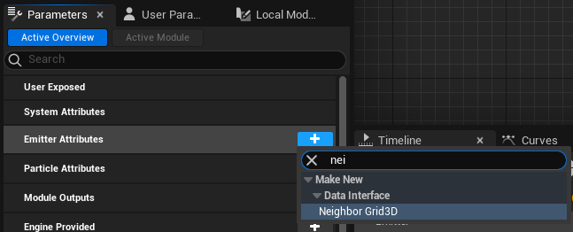
Add Neighbor Grid3D from empty
One data structure we should use is Neighbor Grid3D, we will store our particle indice into grid, for convience of searching neighbor particles in 8 grids around certain particle.
In Niagara System window, find Parameter window (not Details windows), find Emitter Attributes, click “+” button, search neighbor in popup, then you will find Neighbor Grid3D item, confirm.
You know the adding parameters of Niagara System is similar to actor blueprint.
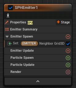
After creating a Neighbor Grid3D parameter, you should drag it into you emitter. Then Neighbor Grid3D will take effect in this emitter.
Using module script from content example
After you add Neighbor Grid3D variable, you should also define some variable about extent, transform matrix, etc. To skip these details at the first time, I copy two modules Initialize Neighbor Grid and Populate Neighbor Grid from offical Content Example.
However, after doing this, I add Spawn Rate and then click Fix issue, try to add Emitter State. But UE log “fail to add emitter state” becuase “could not find location”.
I don’t know why, so I create a emitter from existing copy, and delete redundant module from it. So now I get no error.
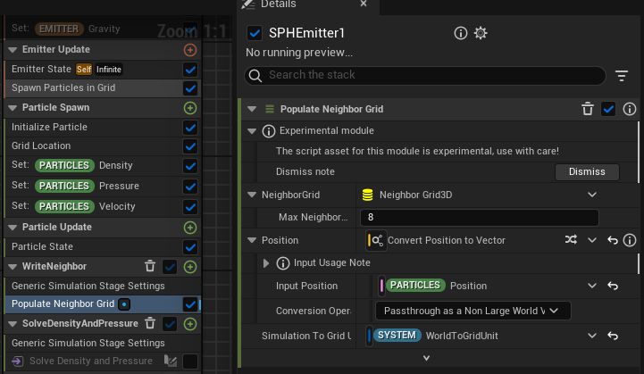
When setup your copied module, be carefull to your default value .
For example, Populate Neighbor Grid has a Neighbor Grid 3D input, its default value is different from your existing Neighbor Grid 3D in your Niagara System.
Setup Parameters and Simulaton Stage
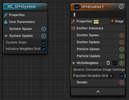
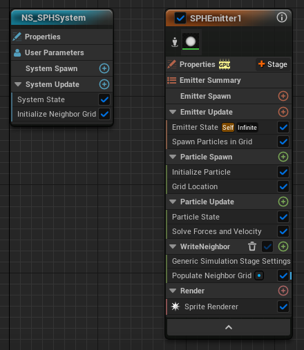
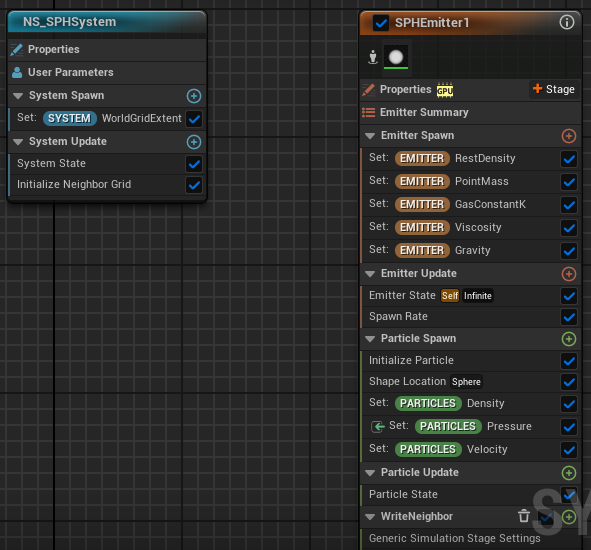
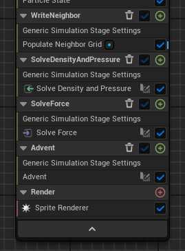
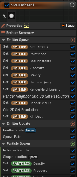
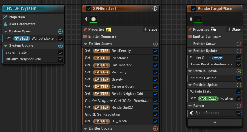
Next we should add some parameters. Here is an overview of Niagara System and you will what is new.
Parameter value:
| Module | Parameter Name | Value |
|---|---|---|
| Set (SYSTEM) WorldGridExtent | WorldGridExtent | (6,6,6) |
| Initialize Neighbor Grid | MaxNeighborsPerCell | 20 |
| Initialize Neighbor Grid | NumCellsX | 25 |
| Initialize Neighbor Grid | NumCellsY | 25 |
| Initialize Neighbor Grid | NumCellsZ | 25 |
| Emitter Spawn | RestDensity | 1 |
| Emitter Spawn | PointMass | 0.05 |
| Emitter Spawn | GasConstantK | 150 |
| Emitter Spawn | Viscosity | 10 |
| Emitter Spawn | Gravity | (0,0,-9.8) |
| Spawn Rate | SpawnRate | 200 |
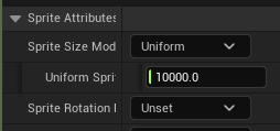
| Initialize Particle | Lifetime | 50 |
| Initialize Particle | Uniform Sprite Size | 0.1 |
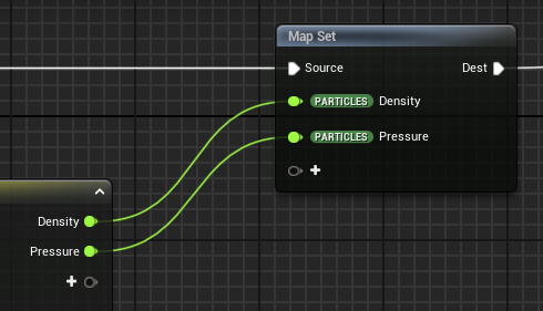
| Set (PARTICLES) Density | Density | 0 |
| Set (PARTICLES) Pressure | Pressure | 0 |
| Set (PARTICLES) Velocity | Velocity | (0,10,0) |
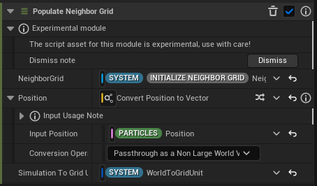
| Populate Neighbor Grid | NeighborGrid | Your Neighbor Grid |
| Populate Neighbor Grid | Simulation To Grid Unit Transform | WorldToGridUnit |
| Solve Density and Pressure | Emitter Name | SPHEmitter1 |
| Solve Force | Emitter Name | SPHEmitter1 |
| Advent | MaxAccel | 10 |
| Advent | MaxVelocity | 30 |
| Advent | WallDamping | -0.1 |
These values are set based on experience. They are only suitable for reference but not necessarily the most appropriate.
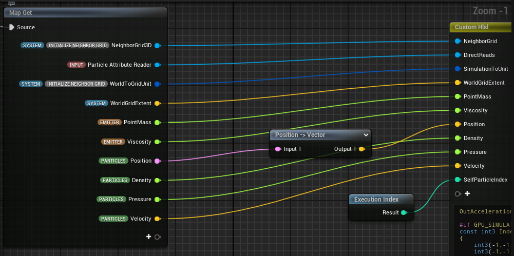
Solve Density and Pressure
Module View
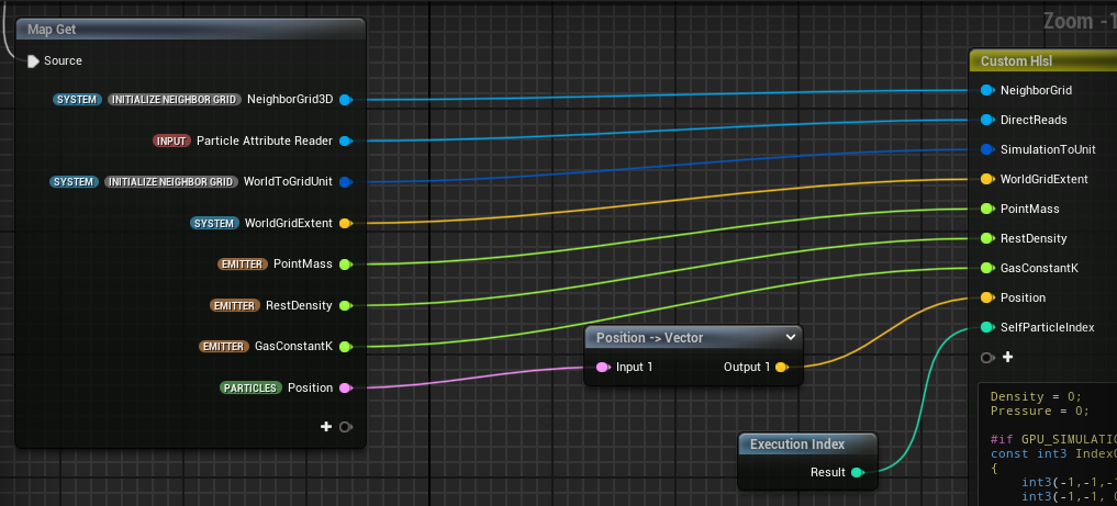
1 | Density = 0; |
Problem: NeighborGrid.GetCellSize return 0
This method has an error, that NeighborGrid.GetCellSize always return 0.
I have post a thread in UE forum,
UE5 Niagara How does Neighbor Grid 3D GetCellSize working? It always return 0
Solution
but now just quickly fix it by passing extra value.
Solution is to add WorldGridExtent input, and calcuate cellsize by myself.
1 | float3 CellSize = WorldGridExtent / NumCells; |
Problem: pow(-0.01, 3) return NaN
After that, I found power of negative number may return NaN, such as pow(-0.01, 3) return NaN.
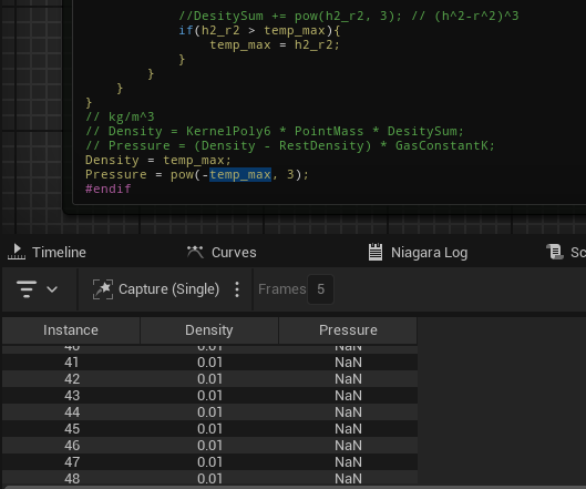
Solution
So solution is add a condition statement r < SmoothRadius, to avoid power of negative number.
Solve Force
Module View
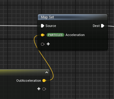
1 | OutAcceleration = float3(0,0,0); |
Advent
Module View
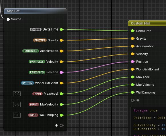
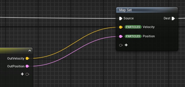
1 | #pragma once |
Problem: Oscillation may be too violent
You may find your particles have violent oscillation and never become idle, which is unexpected.
Solution
Simulation method has common problem about stability, a direct solution is to reduce your timestep.
1 | DeltaTime = DeltaTime / 5; |
However, it will make your particle effect very slow, it is unbearable for gamer.
Or you can increase viscoity, reduce acceleration limit and velocity limit.
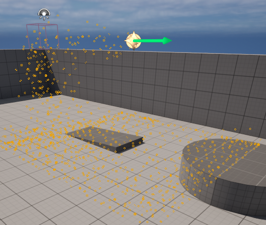
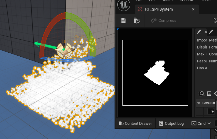
Current Effect
Current effect is as below, the particles should be stacked multiple layer, and have little oscillation.
Problem: Effect doesn’t show up in level
If you drag your Niagara System to your level and then there is nothing show up.
Solution
If particles is too small, then, maybe because of LOD or some built-in engine behaviour, you can’t see it in the level. To make particles visible, you should change Sprite Size.
Render Setup
Traditional method of rendering water surface is marching cube method. It generates density field from particles, then extract polygon mesh isosurface. It can be done on GPU, but very expensive.
Another way is to project all all particles into screen space. A direct idea is using depth buffer, but I think that depth buffer can only tells where the particles are. However, later I learned that normal can be calculated from depth buffer.
Another Neighbor Grid 3D Used for rendering in Screen Space
At first, project all particles into screen space. More specifically, you create an empty depth buffer, then project each particle’s world position into screen space position, and draw a circle with given radius, in the depth buffer, with the particle’s depth. For sure, small depth value will override large depth value.
However, if you draw circle into depth buffer, you may encounter memory access conflict becuase you are running kernel function on each particles. Then each thread may need to write same pixel of depth buffer at the same time. You should take strategy to solve the conflict, such as mutex lock. It definitly hurts parallel performance.
Think in the opposite way, after creating an empty depth buffer, for each pixels in screen space, find particles projected in the screen space position of pixel. To do this, create a new Neighbor Grid 3D, which is used for accelerating searching particles. From the view of occupying space, the Neighbor Grid 3D should occupys full space of screen, so one cell of Neighbor Grid 3D may overlaps with many pixels.
Now kernel function on each pixels may read particles attributes at the same time, but there is not conflict problem.

Use Grid 2D to Store Depth Value
Here Grid 2D is used to stored depth and then write it into Render Target.
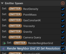
To initialize Grid 2D, you can use bulit-in module Grid 2D Set Resolution. But if can’t find it after clicking plus symbol on the right side of Emitter Spawn, the reason may be you should uncheck Library Only.
Grid2d collection no cellnums setting shown in ue5 niagara
Similarly, you can use built-in module Neighbor Grid 3D Set Resolution to initialize your Render Neighbor Grid 3D.
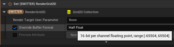
You can also set half float format for Grid 2D.
Texture Render Target and Render Target 2D
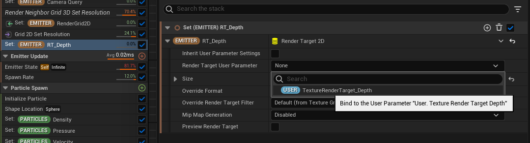
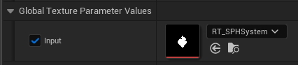
You should be familiar with Render Target file in Content Browser, but you may don’t know how to link it with Niagara System.
First you should create a Texture Render Target with User namespace.
Be caution, it is not Render Target 2D. For example, you can see I create a Render Target 2D named RT_Depth and a Texture Render Target named TextureRenderTarget_Depth.
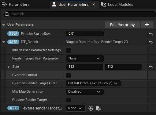
Then crate a Render Target 2D also named RT_Depth with Emitter namespace, drag it into Emitter Spawn to initialize it.
Then you will see, in property Render Target User Parameter, there is only one choice TextureRenderTarget_Depth. It means that you can only assign Texture Render Target as Render Target User Parameter of Render Target 2D.
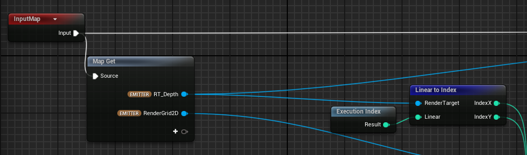
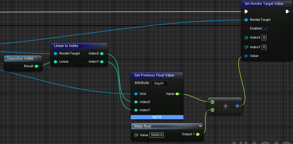
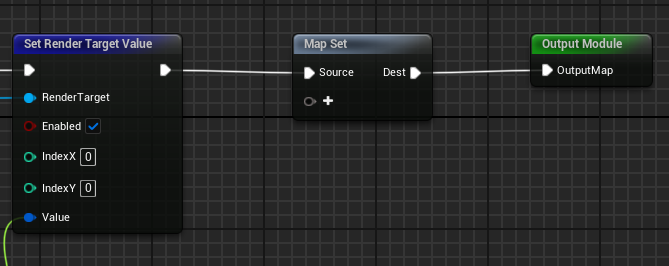
After setting, you validate whether the Render Target is associate with Niagara System immediately. To do this, create a new simulation stage, set Data Interface as Render Target 2D. Create a new module, enter the module, add Render Target 2D in Map Get, drag from Render Target 2D input and search Set Render Target Value in the popup. Create Execution Index block, link to Linear To Index, link IndexX, IndexY to Set Render Target Value. Create Make Linear Color and link to Set Render Target Value. For example, choose a purple color, open your Render Target file from Content Browser, then you will see your Render Target change corresponding to your Make Linear Color block.
Overview
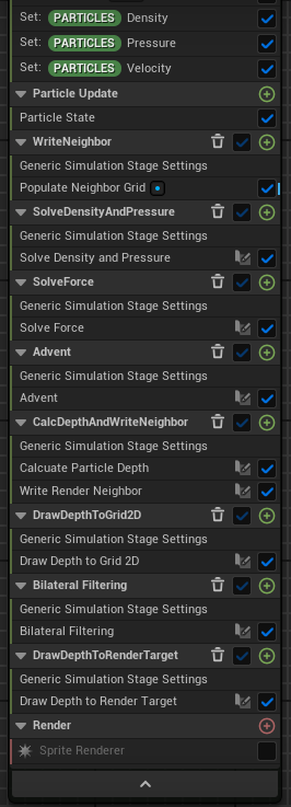
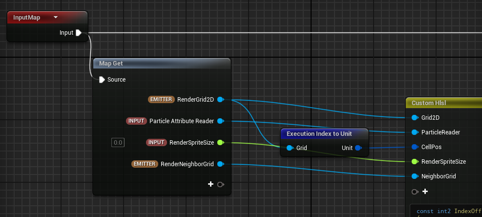
Calc Depth And Write Neighbor
Module View
First module is CalcuateParticleDepth.
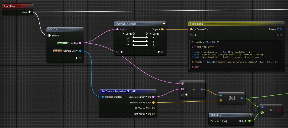
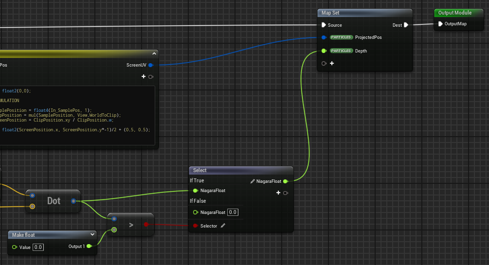
The hlsl is borrow from World Position to Screen UV block. This is about projecting particle’s position into screen space.
1 | ScreenUV = float2(0,0); |
Calcuating depth is simple, in short, it is vector multiples with forward.

You should also check whether the particle is behind camera, if so, then discard.
The second module is WriteRenderNeighbor. This is about storing particles into Neighbor Grid 3D according to particle’s projected position.
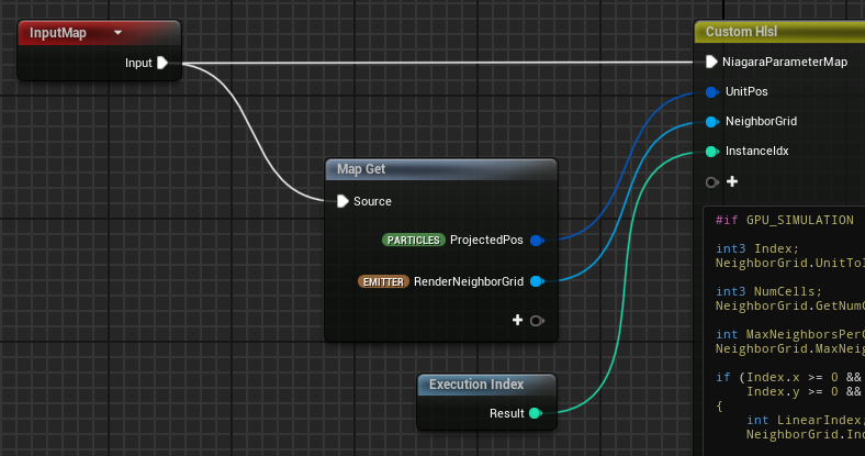
1 | #if GPU_SIMULATION |
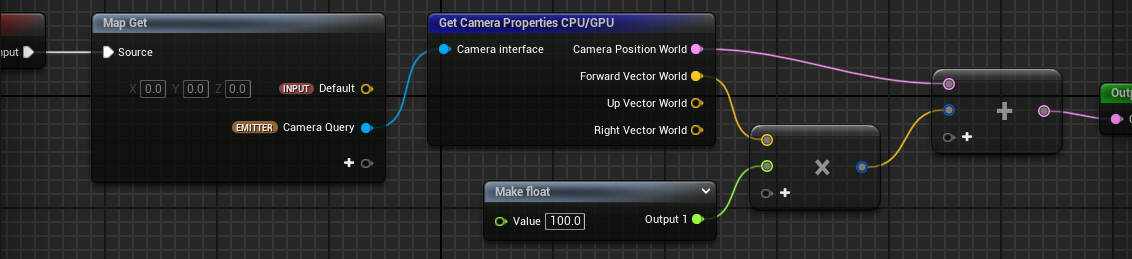
Problem: Capturing result of camera query always located at world origin
Niagara System capturing result of camera query always located at world origin. That means, only when player look at world origin can player see it, no matter where the Niagara System instance is.
For example, in this gif, Niagara System is moving in the world, but capturing result doesn’t move in the Render Target.
Solution
I don’t know it is a bug or not. Maybe it is because I enable Local Space in emitter property. Anyway, it is confusing.
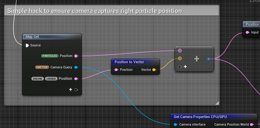
However, simple hack is adding Niagara System position to particle’s position when you are capturing particles.
I have post a discussion in UE forum, maybe someone knows why.
Niagara System capturing result of camera query always located at world origin
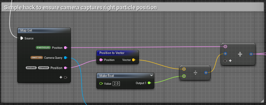
But only add a Niagara System position is not enough. The result position reflected on the Render Target is still not correct.
So after trying, the correct position is particles’ position + Niagara System position / 2.
Although I haven’t said it here yet, if you have set Render Target as Material Input, and link it with opacity mask, you will see:
To observe this, scale of plane should be a litter smaller than it should be.
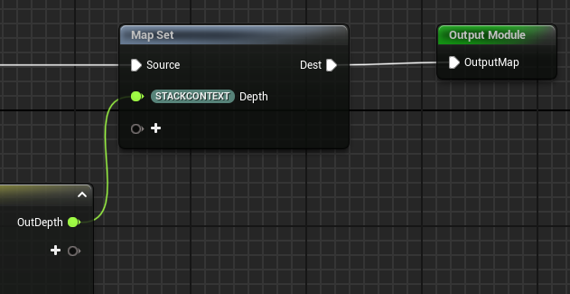
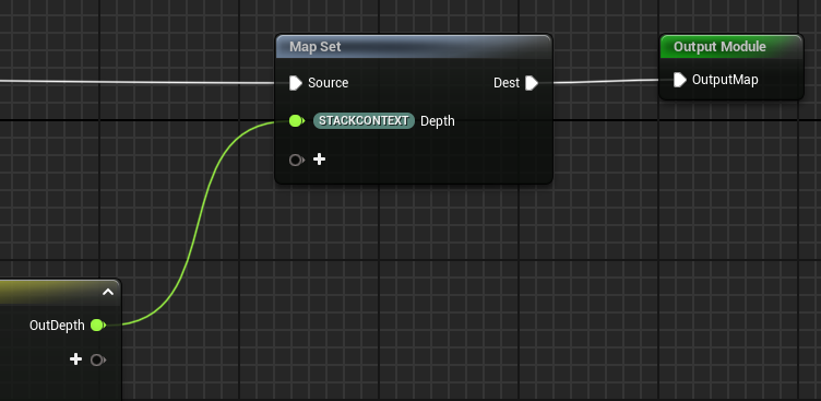
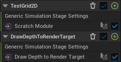
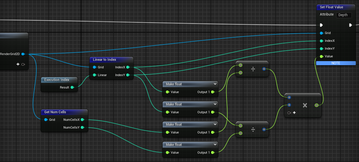
Draw Depth To Grid 2D
Set Iteration Source as Data Interface, and drag RenderGrid2D to Data Interface, then in the module, if you set namespace of a value in map out as STACKCONTEXT, the value will be stored into Data Interface automatically.
Now, if you want for loop pixels, logically you first traverse Grid 2D, stored your desired value into cells of Grid 2D. After travering finished, you write value from Grid 2D to a render target.

If you found your Render Target shows cube-like particle but not sphere, try to adjust RenderSpriteSize from small value to large one.
Module View
1 | const int2 IndexOffsets [ 9 ] = |
There is still concern about we shouldn’t stored particle depth directly, because it is depth at particle cell. What we need is actually depth at cell center.

1 | const int2 IndexOffsets [ 9 ] = |
But I think there is little difference between them.
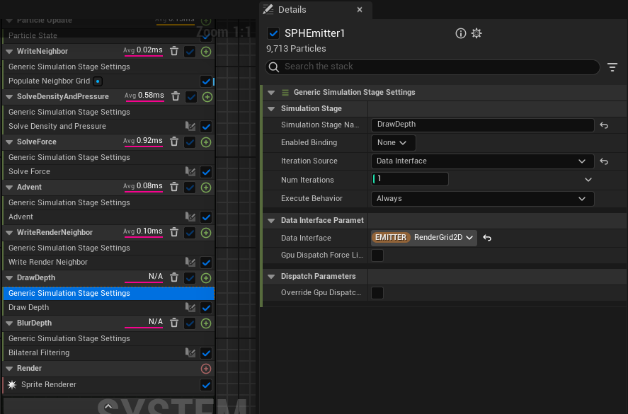
Problem: Performance is N/A
Niagara is compiled successfully, but the running time of a certain simulation stage is N/A.
I have post a question in UE forum.
UE5 Niagara Compilation succeeded but certain simulation stage’s performance time is N/A
Solution
After one day of work, I found the error disappear surprisingly.
From the time I encounter the problem to the time I found the problem disappear, I have done many step, most of them are irrelevant about Grid 2D. The only relevant step is adding a built-in Grid 2D Set Resolution module. But if I delete the module, the performance logging time is still work well. So it is a magic and I don’t want to pay attention to this issue anymore.
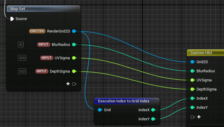
Bilateral Filtering
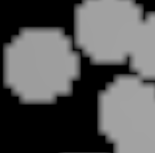
The module does Bilateral Filtering on depth map stored in Grid 2D. Blur will make your depth map smooth, which will make your normal map look less like particles. Gauss Filterign will blur the whole image, but Bilateral Filtering will preserves sharp edges.
Module View
1 | OutDepth = 0; |
Toggle Blur module, you should see the difference.
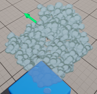
However, blur parameter also matters. Inappropriate parameters are equivalent to you not blurring, and your normal map will end up looking like particles, such as the image above.
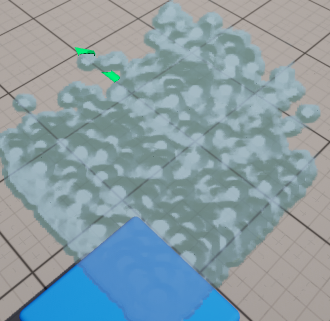
In the last I will show a more natural result, where parameters setting is:
| Name | Value |
|---|---|
| BlurRadius | 5.0 |
| RenderSpriteSize | 3.0 |
| BlurDepthFalloff | 1.0 |
| BlurScale | 0.1 |
Draw Depth To Render Target
Now Data Interface can choose Render Target 2D or Grid 2D.
Module View
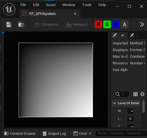
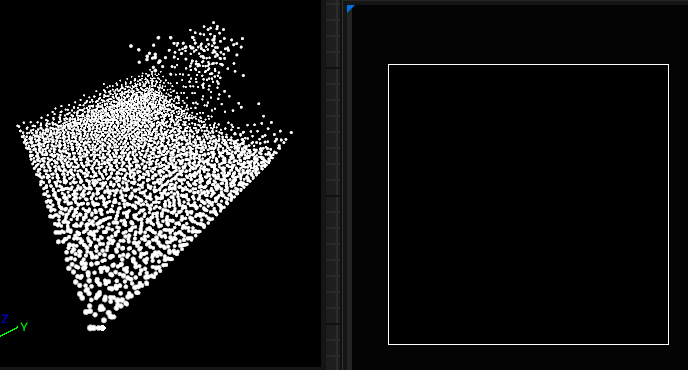
Problem: Only one line in Render Target is white
After drawing to render target, there should be a beautiful depth map in Render Target, but I only see one line in Render Target is white.
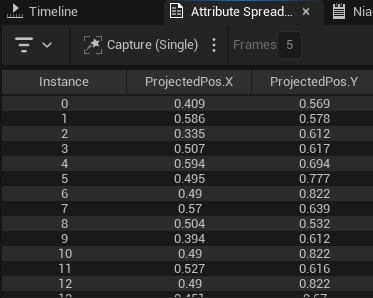
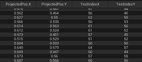
Log the proejcted position stored on particles, and it seems correct, because all of them are in (0,1) and there are not strange values.
Depth values stored on particles are also checked. They are located in (10, 100) roughly, and it is reasonable. My WorldGridExtent is (6,6,6), so distance of camera to particles should be of the same magnitude as grid length, if camera want to see the particles clearly.
Then another reason may be calcuation of index is wrong. Error may located in Write Depth to Grid 2D module or Write Depth to Render Target module.
Firstly I validate Write Depth to Render Target module quickly. I add a test module before Write Depth to Render Target module, add output x*y as Depth.
You can see Render Target perfectly displayed x*y result, so Write Depth to Render Target module has no error. So problem is in Write Depth to Grid 2D module.
In Write Depth to Grid 2D module, type same testing code in the end of custom hlsl, and you will get same result on Render Target.
1 | OutDepth = (float)Index.x/(float)NumCells.x * (float)Index.y/(float)NumCells.y; |
Use CellPos to get same result.
1 | OutDepth = CellPos.x * CellPos.y; |
At least it shows that grid index and CellPos is right.
After I add condition statement between IndexToUse and NumCells, the flashing white line disappear, only pure black left.
1 | if(IndexToUse.x >= 0 && IndexToUse.x < NumCells.x && |
Then I realize that problem may not lies in Grid 2D but in Neighbor Grid 3D.
In fact, if you set -CurrNeighborIdx to depth then you will see pure white in Render Target, it means you never find a valid neighbor.
1 | minDepth = -CurrNeighborIdx; |
I guess particles may not be stored into Neighbor Grid 3D, so I go back to Write Render Neighbor module.
1 | #if GPU_SIMULATION |
So next I have tried other debug method, but still don’t know what is wrong.
Solution
The finally solution is pretty simple: I should drag Neighbor Grid 3D to Emitter Spawn Group to initialize it.
It is confusing me bacause if I use the Neighbor Grid 3D in later module, there is no error.
Anyway, leave it behind.
Problem: Unexpected Render Target Flickering
Right after fix the problem of initializing Neighbor Grid 3D, my Render Target finally have right depth map but unexpected flickering occurs.
The flickering in the recorded gif is not due to image compression.
I have searched UE forum:
Niagara particles flickering in latest .26 release
Their solutions:
-
Reduce spawn rate
-
Reduce particle emitter sphere radius
-
Enlarge
Fixed BoundsinEmitter Properties -
Change to
CPU Simualtion -
Set the
Sort ModetoView Depthin Sprite RendererIt mey be problem about translucent sorting
-
Enable
Camera Distance Cullingin Sprite Renderer, adjust max camera distance -
Change the mesh size much smaller
However, in this case, it is not about translucent particles, because it is not about capturing particles actually. The camera capture only capture particles’ depth. Then simulation stage writes the depth into Grid 2D. So my situation may be totally different from other.
Solution
Finally I don’t want to waste my time on the engine bug, so I give up trying.
But just after an hour I come back to work, the problem disapper amazingly.
Nothing to say with the kind of situtation.
Updated: After a few days, I happen to find the flickering reason: Render Target is switching between scene capturing result and Niagara System capturing result. You can see it clearly in my record.
So it is engine bug, not my fault.
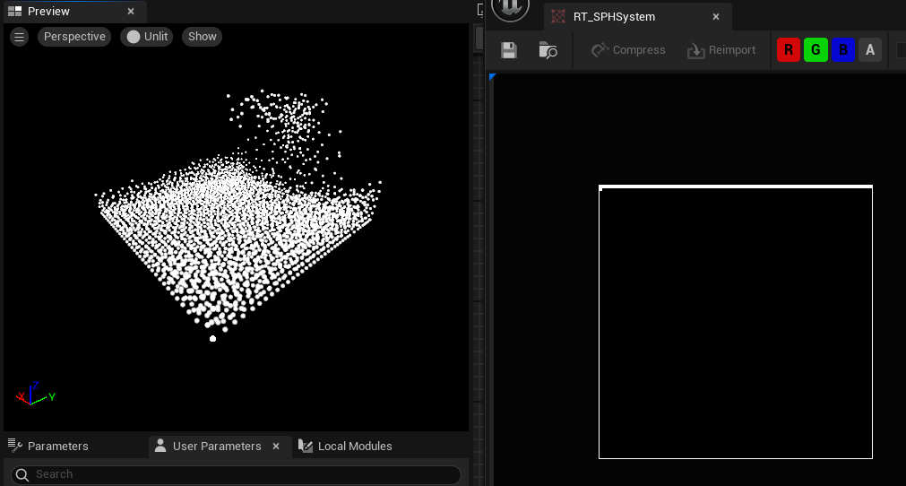
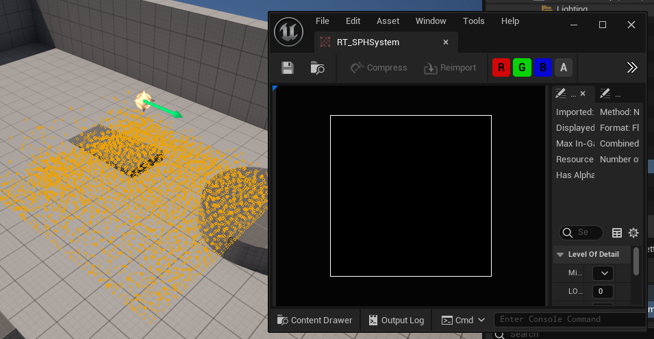
Problem: Render Target has content in Niagara System Preview but no in the level
After I found Render Target doesn’t flicker, I put the Niagara System into level. Becuase my WorldGridExtent is very small, which is (6, 6, 6), so I had to scale the Niagara System to (100, 100, 100) size. I had talked before sprite size should also be large, but now we don’t need sprite to show where the particles are, we only need a plane to show fluid rendering result, so we can disable sprite renderer in the SPH emitter. But as I continued to make the fluid material, I found that Render Target has content in Niagara System Preview but no in the level.
Solution
It recalls me that small particles is invisible, so I guess that even though we scale Niagara System to make particles visible, in the camera view, it doesn’t apply scale transform to particles in the level. Camera is always capturing particles of original size, so particles move in small space. While small size particles is invisible, or I guess it is also related with small spacing. Combining these two factors, which makes camera can’t capture particles in the level.
To solve it, the only way is to change WorldGridExtent and adjust SPH parameters to adapt with new extent. This is a torturous thing, so after I obtained a seemingly acceptable result in the small extent, I did not adjust the parameters in the large extent. Now, it seems like an unavoidable task.
If only want to validate the camera problem, we can leave the quality of visual effect behind. Practice shows that the assumption is right. Make WorldGridExtent larger, then particles move in a larger space, then camera can capture them effectively.
New parameter:
| Module | Parameter Name | Value |
|---|---|---|
| Set (SYSTEM) WorldGridExtent | WorldGridExtent | (200,200,200) |
| Emitter Spawn | RestDensity | -50 |
| Emitter Spawn | PointMass | 10 |
| Emitter Spawn | GasConstantK | 100 |
| Emitter Spawn | Viscosity | 25 |
| Advent | MaxAccel | 200 |
| Advent | MaxVelocity | 100 |
| Advent | WallDamping | -0.8 |
After this parameter adjustment, I found a way to quickly obtain the appropriate parameters: first increase the pressure, such as increasing the gas parameters, and then increase the viscosity. Finally, you will get an effect that looks a bit like a fluid. Although this cannot avoid the so-called jelly water, at least you must first be able to obtain a stable effect before you can start optimizing it.
Problem: Move Niagara System but particles are blocked at border
Solution
Enable Local Space in Emitter property, then all particles’ position are calcuated in local space. In other word, the particles’ coordinate follows actor but not world coordinate.
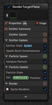
New An Emitter to Emit Plane for rendering
You should create a plane to show the rendering result. It can be created in Niagara System or in world level. The former looks nice because it hides details into Niagara System itself.
To do this, new an emitter to emit a plane sprite. The sprite lifetime should be long enough, so it can be set as LoopDuration
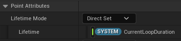
The plane sprite should be located between camera and Niagara System, and should be large enough to cover the whold Niagara System.
There is room to decide specific distance from camera to plane. Here I choose 100.
Overview
Problem: Emitter turns into balck in the Niagara System Overview and Sprite doesn’t show up
Sometimes, my plane emitter turns into balck in the Niagara System Overview and plane sprite doesn’t show up.
Solution
It may be UE bug, restart UE project will solve the problem.
Create Fluid Material
Next you should add a material to your plane.
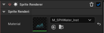
This material should have a TextureSampleParameter2D paramter, to get Render Target.
Create an instance of the material, then you can assign Render Target to the instance parameter.
Get Normal from Depth Map
There is method to get normal from depth map, but I haven’t pay time to understand it.
Screen Space Fluid Rendering for Games - Nvidia
Unreal has built-in Normal From Height Map block, but it only receives Texture 2D object. So I copy the content from it and replace the Texture 2D part with Input parameter.
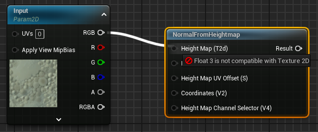
Becuase I store depth to RGB of Render Target, so when you take depth from Render Target, you should choose the same channel.
Get Opacity Mask from Depth Map
To mask space without fluid, sample from Render Target and link it directly to Opacity Mask.
But if you want other objects to cover fluid, you should compare SceneDepthWithoutWater with fluid depth. If SceneDepthWithoutWater is smaller than fluid depth, then other objects can cover fluid.
Single Layer Water Material
To use SceneDepthWithoutWater block, you should set your Shading Model to Single Layer Water.
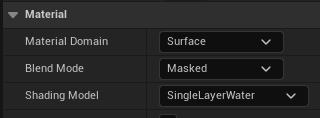
To compile the material, you should have Single Layer Water Material block.
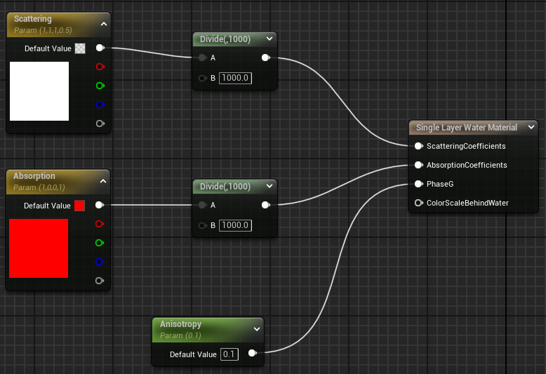
Problem: ScatteringCoefficients Node Link in Single Layer Water Material breaks alpha blending
I have fed an occlusion-tested depth into the alpha. The specific method of the occlusion test is, water depth is compared with Single Layer Water Material block, output depth is 0 * water depth = 0 when water is covered by other objects, 1 * water depth = water depth when nothing to block.
If I link a input value into ScatteringCoefficients node in Single Layer Water Material block, then alpha blending will be break.
If I break ScatteringCoefficients node link, then alpha blending will be correct.
I have post a thread in UE forum waiting the answer.
ScatteringCoefficients Node Link in Single Layer Water Material breaks alpha blending
Solution(?)
Don’t use ScatteringCoefficients node.
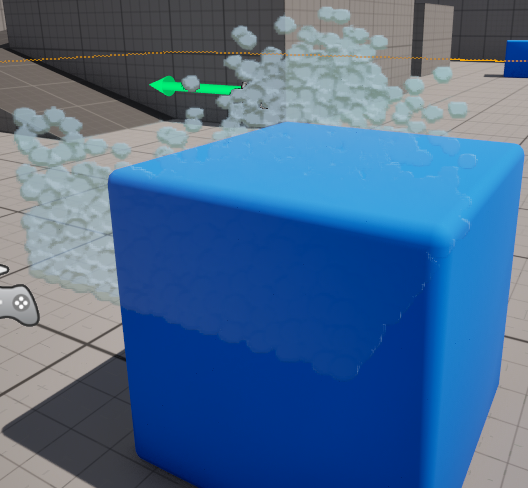
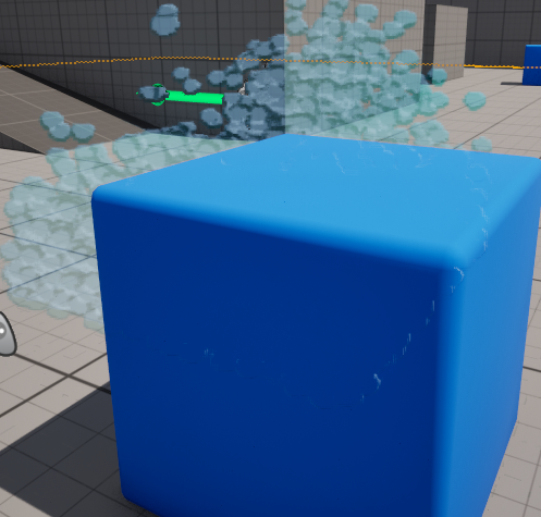
Problem: Water border shows up ignoring occlusion
In the image above, you will see water border shows up ignoring occlusion,it is because depth map in Render Target appears weird blur margin.
Current stage I don’t have a solution to deal with this. Maybe a material hack can takes effect.
Final Result
Although it doesn’t look very good, at least it has normals that look reasonable. How to make it look better after that is a matter for the shader.